Welcome to My RoboSumo Blog
Introduction:
This blog’s purpose is to document the work my team and I have done on the RoboSumo project each week. It will include descriptions, images and videos of work done and progress made. The project is to design a robot to ‘Battle’ other robots in a circular ring with black center and white border. The robot should be entirely autonomous requiring no human input other than to turn it on or off. It shouldn’t leave the ring and cannot exceed 10cm x 10cmx 10cm in length, width, height and 500g in weight.
LED Control:
In the first week we experimented with the Arduino Nano we were to us to control the robot. We did this by writing Arduino code to control red LED’s to express a number in binary.
This took multiple steps, first we controled the switch using a switch. Shown in figure 1 and the code controling it. There were errors in creating this code, but troubleshooting our way through the problems helped us with or understanding of how the logic of c works, as well as how to better prepare our design process going forward.
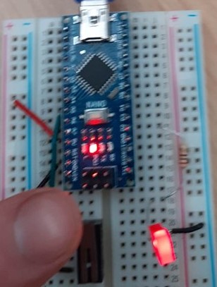
LED with switch
Next we changed the code to support the switch as a latch, this is shown below in a video of it working. In this case the latch worked well.
Once we had completed the previous challenge we then had to make the circuit produce two binary numbers using two LED’s, one representing 0 and the other 1. We completed this with the program inteed detecting the pattern.
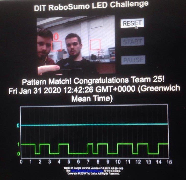
LED program flashing numbers in binary
Motor Control:
Summary of Motor Control:
We experimented with controlling motors. This went well, we were able to get both motors working forwards and backwards, in sync with one another. This is good as all the motors have to do is go backwards and forwards, as using this we can turn the robot by going forward on one motor and either backwards or stopping the other motor.
The motors are controlled by the Arduino nano, the digital
pins (D2-5), are connected to the power chip below, with the pins set to OUTPUT.
The power chip can take the low voltage digital input form the Arduino and can amplify this so as to provide more energy to power outside devices, i.e. Motors. Connecting wires are shown in pink and blue in the figure 3 below.

Motors and Arduino.
Multiple code attempts were needed to give the desired functionality.
Motor Control Version 1:
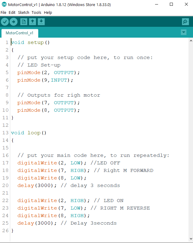
The Code above, MotorControl_v1, was our first attempt at controling a motor. For this we only used one motor to keep it simple until we had the motor working. The code includes one motor on D 7 & 8, an LED on D2 and the Infra-red sensor (discussed in the next section) on D9, it wasn’t used yet. The code first drives the motor forward for 3 seconds with the LED off, then it drives it in reverse for 3 seconds and the LED is on. The LED was used the make it easier to identify if the motor was in forward or reverse.
This program worked perfectly and we had few issues ith developing it, not surprising as it is a simple program, yet it was useful as we did make some syntax errors and simple mistakes, which definetly helped refresh our memory of C programming and its logic and structure.
MotorControl_v2:
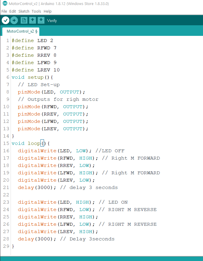
Sincew we got the one motor working we then moved on the implementing the second and using the #define functionality. RFWD = Right Forward & LREV = Left Reverse, etc.
For this we haven’t included any sensors to the system yet, we added the second motor and added it to the same functions as in MotorControl_v1 but now with two motors and we redeclared the outputs as #define. This program gave use the desired functionality of both motors forward for three seconds with LED Off and reverse for three seconds with the LED on.
Son now we had found how to make two motor’s in forward in reverse, playing with this we can now make the robot go forward, backwards, left and right, i.e the robot has manuverability.
Light Sensor/ Infra-Red Sensor:
This is integral to the system as the robot must not leave the ring, a large black circle with a white border. The colour sensor is good for detecting this, and in general it gives us more information about what the environment around the robot, allowing for potentially better control . The only way to do this is with this sensor. As of now this sensor isn’t properly intigrated into the system.
Ultra Sonic Sensor/Distance Sensor:
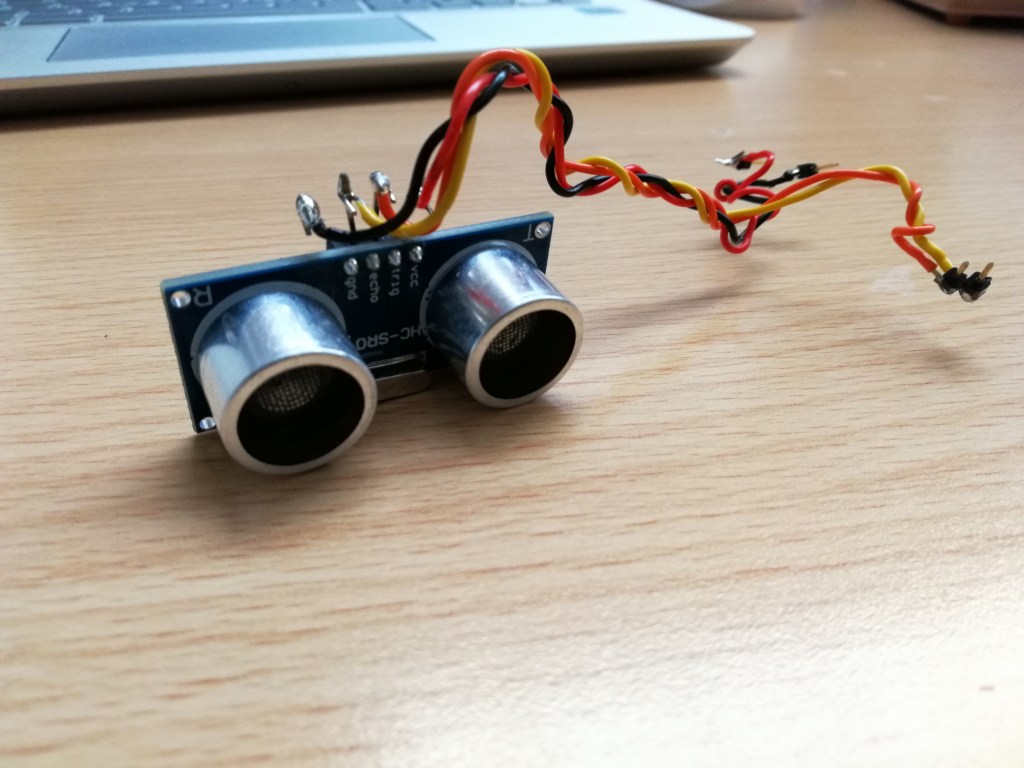
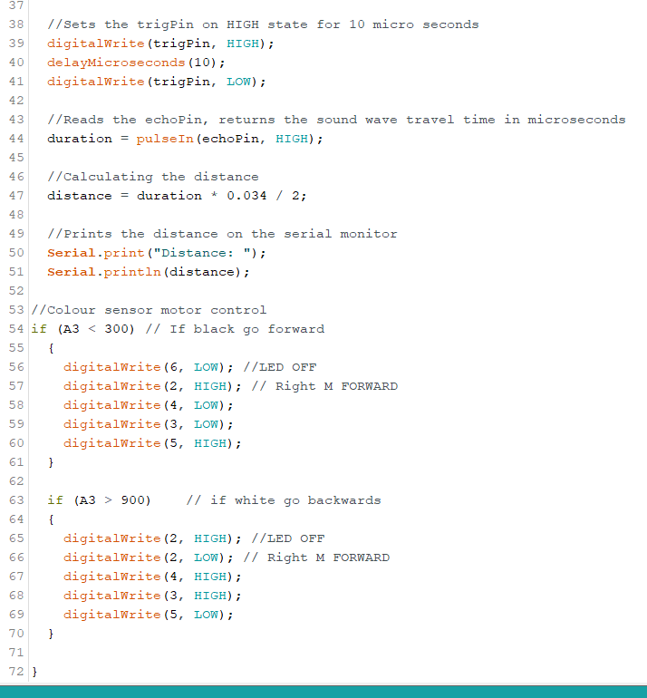
We are now attempting to integrate an Ultra-Sonic sensor to our system to allow it to read distance(s). This is very useful as it gives us a all be it very limited ability to ‘see’ what is ahead. The sensor is a HC-SR04, shown below, it has a transmitter and a receiver or trigger and echo.
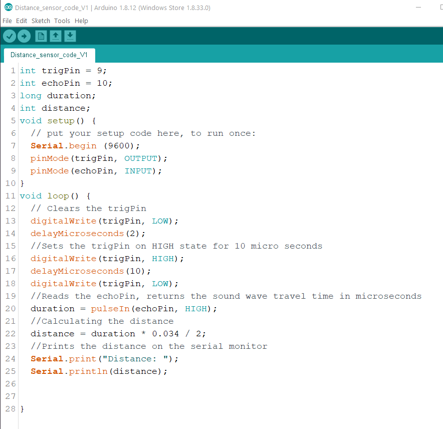
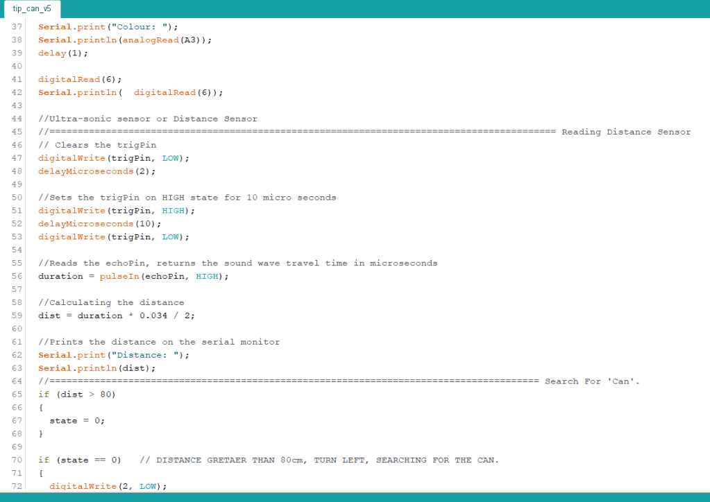
The code above was the set-up for the sesnor and the calculation of the distance in Centimeters.
The trigger pin is connected to D9 and th Echo to D10. There are two variables needed durarion and distance. Duration is what the sensor measures, it is the lenght of time it takes for the pulse to bounce of the object/obstruction and then travel back to the sensor’s reciever/ echo pin. To get the distance we must multiple the duration by 0.034/2. This formula was used as it was what was recomeneded in the sensors data sheet.
The program worked well, it accuratly calculated distances, we checked using a ruler. Unfortunatly within approximatly 2cm the sensor becomes inaccurate it can read anything from 3cm up to 1023 cm. I believe this is due to the gap between the trigger and the echo. This shouldn’t be too much of an issue, for tip the can it would have been nice if the sensor was accurate all the way to 0cmor 0.1cm as we could avoid using a switch to tell when the robot has made contact with the can and instead use the sensor. This could be done by mounting the sensor more than 2 cm from the front but I don’t believe this is a reliable way of determining if the can has been tipped. .
Tip The Can Challenge:
Once we has the motors and snsors working, reading data and controllling the motors we began work on the “Tip the Can” Challenge. This challenge is to build a robot that can search for the can and then advance towards it, touch it relativly gently and quickly. I.e it should stop when it touches the can and not continue driving into it.
For this functionality we needed some way for the robot to detect the can. We contemplated using the ultra-sonic sensor to detect when the can was touched, i.e distance = 0, but the sensor is unable to read distances of less than 2cm, from our tesing, at 2cm or less the sensor can ‘throw out’ random distances from 5cm – 1023cm. So this elimitaed using the sensor at the front of the robot. We considered mounting it 3cm back from the front and programming it to stop and reverse when distance equals 3cm. But throught testing we found this to be inpractical and unreliable as the sensor had to be ,ounted quite high up meaning if there was a lower level obstruction or ‘can’ it wouldn’t detect it.
We tried using manufactured switches, such as limit switches, but found them difficult to trigger as if the robot hit at even a slight angle it would fail to actuate the switch and it had to hit the can quite hard meaning the can may not accept that as a tip but as a hard hit which was unacceptable. So we decided to make our own swith using two wires, it is shown in the picture below.
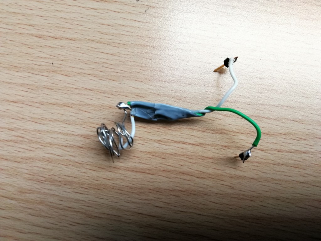
This switch worked much better as we could increase the surface area of the contact so as to eliminate the problem we were having where the the switch wasn’t triggered.
There was some trial and error improved on the design of the switch to make it work best. For example if the gap between the wires was to big it didnt always trigger. If to small it could trigger prematurly. We tapped the wires together as you can see this helped give it a bit more structural integrity so it wouldn’t trigger accidentally. We also had to strip a larger length of the wire and make it into a make-shift coil to increase the Size of the contact area making it more reliable for tipping the can from wider angles than other wise.
Now we have all the components required to make the robot and we can begin putting it all together and finalising the code to have all the required functionality. Much of the code is already done but must be put together into one file. We felt assembling all the components and making them work was an important element of the design process as it is much more practical and is better practice to put working components togther than to try and make them all work for the first time as one large system. This would make troubleshooting immeasurably more difficult.
The first step was to integrate the Ultra-Sonic Sensor and IR Sensor into the motor control program. This allows us to implemet real control as the robot is able to “see” what is infront of it. Meaning we can implement functions instructing it what to do if it detects an object infront of it, i.e. the can.
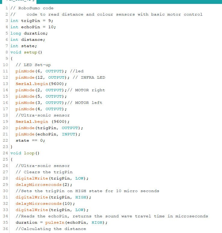
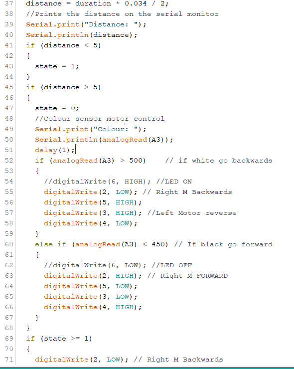
We Implemented it with some trial and error into the below code.
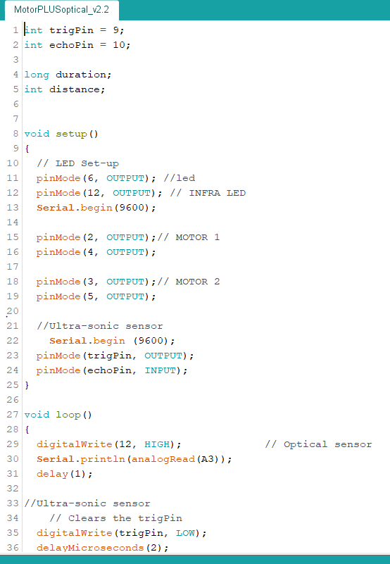
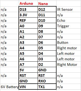
Now that we had the motors being controlled by the IR Sensor we could trey implement the Ultra sonic sensor in aswell. The connections to the arduino we used are also shown below.
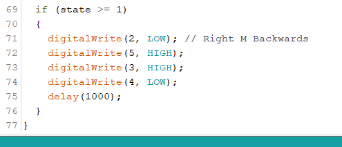
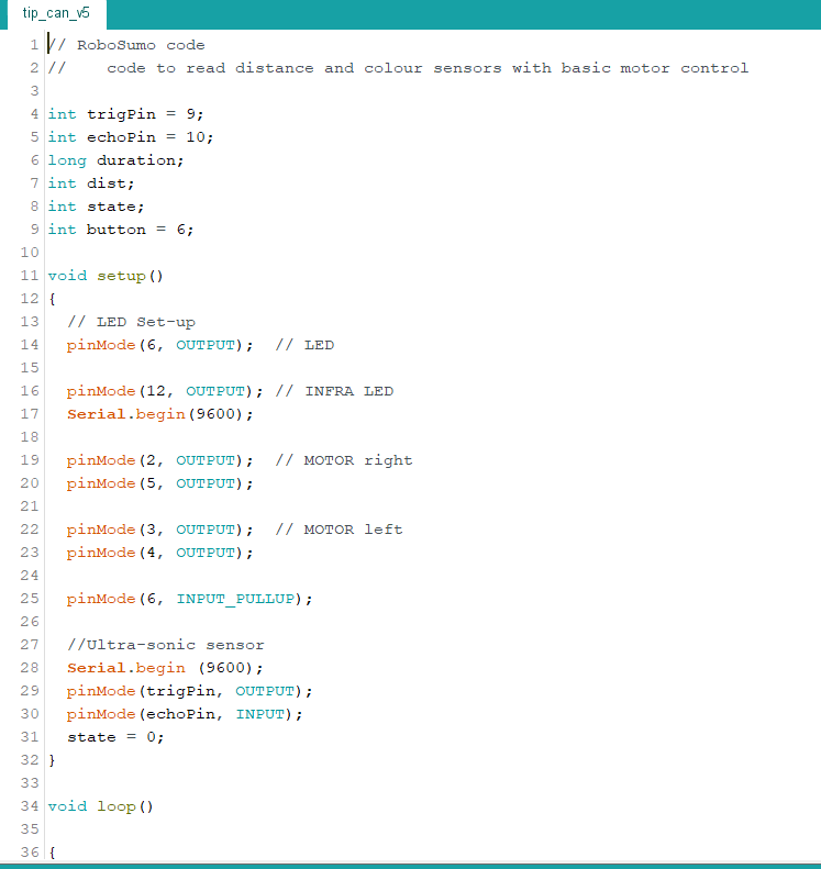
Now that we had all the elements execpt the button implemented and working togther we could work on making the final ‘Tip the Can’ Program’
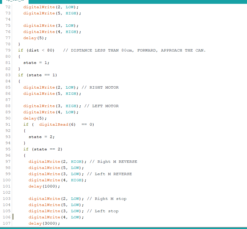
For the challenge the robot must turn on the spot to find the can and once it has found it it must advance towards it, touch it and retreat.
With much trial and error and modivication we managed to create the below program which completed the challenge with a top 10 finishing time in the first week of the challenge of 8.6 seconds.
Conclusion:
We as a team we completed the tip the can challenege and finished it well, competing the challenge int he first week and scoring in the top 10. We could have scored higher if we had increasing the voltage supplied to the motors, we considered this for the second week but our lecturer said that those efforts would be better spent on the final challenge which we agreed with, unfortunatly due to the lock down this turned out to not be possible.
Over all this project was very enjoyable, and of course frustrating at times but hey thats engineering, if it was easy what would be the point. I gained valuable skills in Engineering Design and Practice as well as teamwork, as we had to work togther to create a plan of attack and execute said plan. We started with each component within the system and working forward from there to implement them altogether to create the final product, from motors to sensors to finally how to use the information given by the sensors to create a fully autonomous robot capable of locating and then advancing on the can, to the delicate touch and reverse procedure. Completing the challenge in 8.6 seconds.
Finally I am over all happy with the performance of the team and the robot and belive it is very unfortunate that we couldn’t progress to the Robosumo challenge as I think we could have made a great robot and really competed for top spot.
Follow My Blog
Get new content delivered directly to your inbox.
